Technical Bulletin 102
Location of protective equipotential bonding on gas installation pipework in domestic premises.
Date issued: 3 September 2018
This Technical Bulletin provides guidance to Gas Safe registered businesses/engineers on the requirements for the location and connection of protective equipotential bonding for gas installations in domestic premises.
Note: This version of Technical Bulletin (TB) 102 replaces the version originally published on 30 September 2016, which is now withdrawn. This version has been reviewed and revised where appropriate to ensure that it remains both current and relevant.
What do legislation and industry standards require?
Regulation 18(2) of the primary legislation concerning the safe installation, maintenance and use of gas systems and appliances (the Gas Safety (Installation and Use) Regulations 1998) states: “Any person who connects any installation pipework to a primary meter shall, in any case where equipotential bonding may be necessary, inform the responsible person that such bonding should be carried out by a competent person.”
Note 1: Similar requirements apply in other geographical areas covered by Gas Safe Register. For details of current gas safety legislation, building legislation and industry standards for the geographical areas covered by Gas Safe Register, see the Legislative, Normative & Informative Document List (LNIDL)* by logging into your online account at :https://www.gassaferegister.co.uk/sign-in
BS 7671** Clause 411.3.1.2 (Protective equipotential bonding) requires: In each installation, main protective bonding conductors complying with Chapter 54 shall connect to the main earthing terminal extraneous-conductive-parts including the following:
- (i) Water installation pipes
- (ii) Gas installation pipes
- (iii) Other installation pipework and ducting
- (iv) Central heating and air conditioning systems
- v) Exposed metallic structural parts of the building.
Metallic pipes entering the building that have an insulating section at their point of entry need not be connected to the protective equipotential bonding.
Connection of a lightning protection system to the protective equipotential bonding shall be made in accordance with BS EN 62305.
Where an installation serves more than one building, the above requirement shall be applied to each building.
To comply with the requirements of these regulations it is also necessary to apply equipotential bonding to any metallic sheath of a telecommunication cable. However, the consent of the owner or operator of the cable shall be obtained.
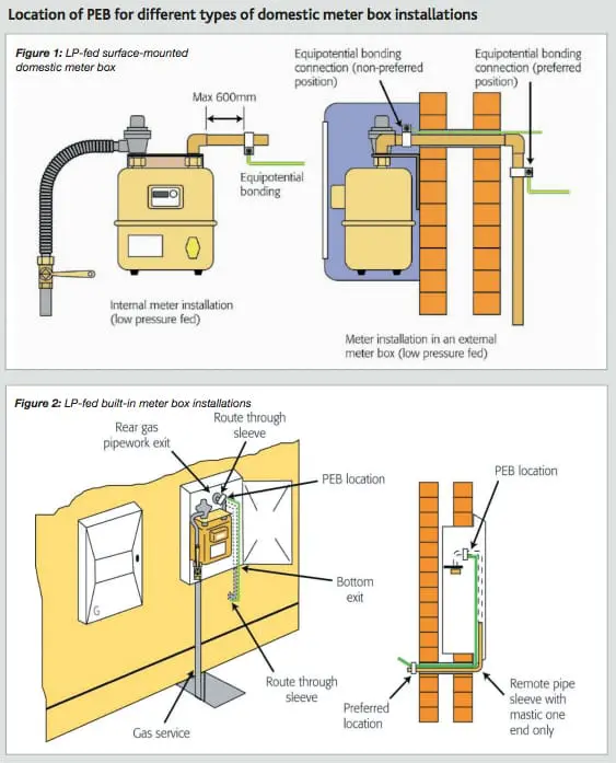
If PEB is required by BS 7671, Clause 544.1.2 states: The main protective bonding connection to any extraneous-conductive-part such as gas, water or other metallic pipework or service shall be made as near as practicable to the point of entry of that part into the premises. Where there is a meter, isolation point or union the connection shall be made to the consumer’s hard metal pipework and before any branch pipework. Where practicable the connection shall be made within 600mm of the meter outlet union or at the point of entry to the building if the meter is external.
Therefore, the preferred position for the PEB is attached to the gas installation pipework where it enters the property. However, this method is not always practicable because of the installation method used to allow the gas installation pipework to enter the building without being visible. As an acceptable alternative, the PEB may be located within an external meter box, connected to the meter outlet pipe, before any branch or tee. However, it is essential that the bonding cable does not interfere with the integrity of the meter box/ compartment and the sealing of any pipe entry sleeve.
Additional guidance is also given in BS 6891***, Clause 8.4.3.2, which states: The main protective bonding conductor (main equipotential bonding connection) shall be connected to the gas consumer’s fixed rigid pipework on the outlet of any primary meter installation, if fitted:
- a) As near as is practicable to the point of entry into the premises
- b) Before any branch in the pipework
- c) In a position where it is accessible, can be visually inspected, and fitted with a warning label stating: “Safety electrical connection. Do not remove”, and
- d) By a mechanically and electrically sound connection which is not subject to corrosion.
The main protective bonding conductor (main equipotential bonding connection) shall not be directly connected to any pliable corrugated (stainlesssteel) tube or pliable connectors from the outlet of the primary meter installation.
Note 2: Similar guidance is given in IGEM/UP/2 Edition 3****.
BS 6400 suite of standards – requirements
Particular guidance is also given in the BS 6400*****/****** suite of standards, which cover the installation requirements for domestic-sized natural gas and LPG meters for both low-pressure-fed and mediumpressure-fed installations.
Note 3: The following definitions apply to this TB:
- A LP-fed gas supply is one where the service pipe/service pipework operates at a design minimum pressure not exceeding 75mbar.
- A MP-fed gas supply is one where the service pipe/service pipework operates at a design minimum pressure exceeding 75mbar and has a maximum operating pressure that does not exceed 2bar.
- ‘Service pipe’ means a pipe for distributing NG to premises from a distribution main, being any pipe between the distribution main and the outlet of the first emergency control valve (ECV), downstream from the distribution main.
- ‘Service pipework’ means a pipe for supplying LPG to premises from a gas storage vessel, being any pipe between the gas storage vessel and the outlet of the ECV.
Clause 6.9.2.9 of BS 6400-1, which covers LP-fed NG meter installations, states: Where the protective bonding conductor connection is made inside a built-in meter box, the cable shall leave the box either through a purpose-provided rear entry sleeve (spigot) or via the bottom exit and not by drilling or piercing the box.
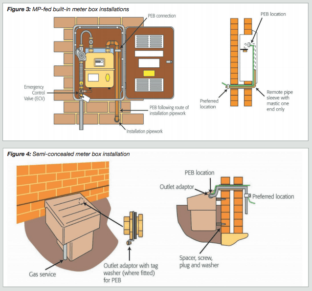
Clause 6.14.6 of BS 6400-2, which covers MP-fed NG meter installations, states: If a meter housing is fitted to or in a wall of a property, there shall not be any aperture or spigot constructed, or subsequently made, in the box which would allow gas to enter into any cavity or the property. In particular there shall not be any aperture constructed in the back of the housing for any purpose.
Additionally, Clause 6.14.7 of BS 6400-2 states: Installation pipework or cables shall not directly enter the property from the meter housing. The note to clause 6.14.7 states: This means that installation pipework or cables have to exit the meter housing before entering the premises.
BS 6400-3, which covers both LP-fed and MP-fed LPG meter installations, provides the same guidance as BS 6400-2 (clauses 6.14.6 and 6.14.7) – this is reflected in clauses 6.11.6 and 6.11.7 of BS 6400-3.
Additionally, Clause 6.11.11 of BS 6400-3 states: Where the main equipotential bonding connection is made inside a built-in meter box:
- a) for a MP installation, the cable shall enter/leave the box via the bottom exit and not by drilling or piercing the box
- b) for a LP installation the cable shall enter/leave the box either through a purposeprovided rear entry sleeve (spigot) or via the bottom exit and not by drilling or piercing the box.
Therefore, from the guidance published in the BS 6400 suite of standards, it can be seen that where a MP-fed meter installation is installed in a built-in, or surface-mounted meter box, neither the installation pipework nor the PEB cable can enter the property directly from within the box itself and must firstly exit the box through a purposeprovided exit on the face of the building, before then entering the property. This requirement is illustrated in Figures 1, 2, 3 and 4.
Can the PEB cable be routed through the gas pipe sleeve in the meter box?
The connection may be made within the meter box, but it is essential that the PEB cable does not interfere with the integrity of the box/ compartment. In the case of a LP-fed meter installation, where the rear entry sleeve of the meter box is used, the PEB cable can also be routed through the sleeve, but it is essential that the sleeve is sealed appropriately with a non-setting, fire-resistant compound, between the sleeve and around both the installation pipework and the cable.
Note 4: For further guidance on the installation of gas meters, see TB 003, TB 004, and TB 040, by logging into your online account at: https://www.gassaferegister.co.uk/sign-in
Note 5: For general information about the process behind the development of Gas Safe Register Technical Bulletins and the expectations for all stakeholders, see TB 1000******* by logging into your online account at: https://www.gassaferegister.co.uk/sign-in
Bibliography
* LNIDL – Gas Safe Register Legislative, Normative & Informative Document List
** BS 7671: 2018 – Requirements for electrical installations
*** BS 6891: 2015 Specification for the installation and maintenance of low-pressure gas installation pipework of up to 35mm (R1¼) on premises
**** IGEM/UP/2 Edition 3 – Installation pipework on industrial and commercial premises
***** BS 6400 suite of standards – Specification for installation, exchange, relocation, maintenance and removal of gas meters with a maximum capacity not exceeding 6m3 /h: • Part 1: Low pressure (2nd family gases)
****** BS 6400 suite of standards – Specification for installation, exchange, relocation and removal of gas meters with a maximum capacity not exceeding 6m3 /h: • Part 2: Medium pressure (2nd family gases) • Part 3: Low and medium pressure (3rd family gases)
******* TB 1000 – An introduction to Gas Safe Register Technical Bulletins
Download Technical Bulletin 102 here: Technical Bulletin 102